


Wireless LED Blackflash Extender for Homebrews or Commercial
 02-06-2014 | 09:41 AM
#1
Thread Starter
Spike
Joined: Jul 2011
Posts: 45
Likes: 0
Got to playing with this a few weeks ago. Wanted to build a wireless blackflash extender that can be added to a homebrew camera as well as a commercial camera. I found a thread on here where Roger (TCScout) had done some work with one earlier. So I took his info and started building on it. Here is a link to his thread:
http://www.hagshouse.com/forums/inde...howtopic=34448
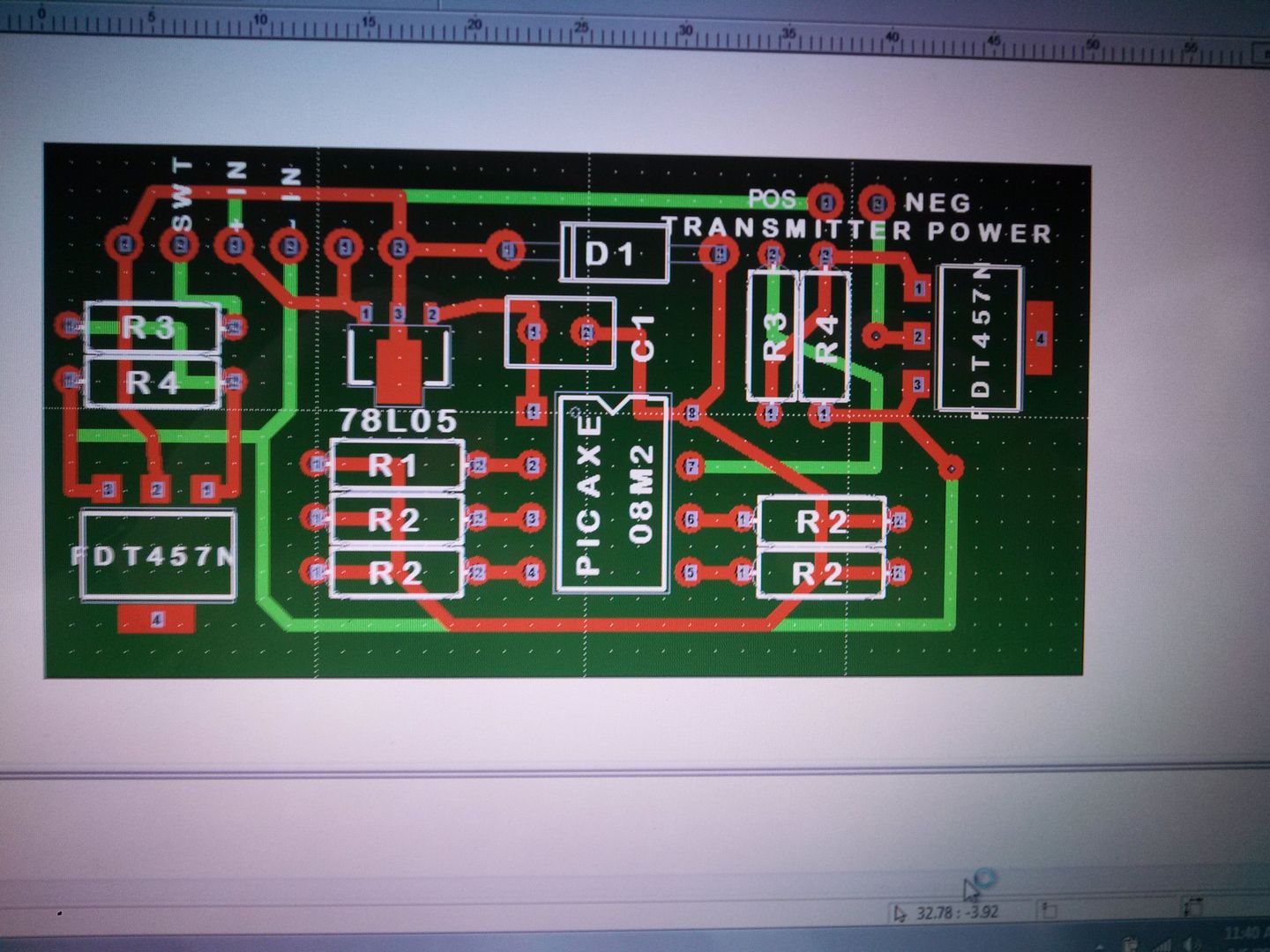
So I started building on what he did. Had some PCB boards built. Man these things work great. Out to 80 feet it works 100% of the time. Adding one to a Homebrew is a peice of cake. No worries at all there. So I decided I wanted to add one to a commercial camera. I got my hands on a UWAY VH200B Blackflash commercial camera and cracked it open. Mounted the transmitter and transmitter board inside it. The UWAY VH200B works on a 10.5v system. So I found some positive and negative power points and wired them in. Next I had to find a power source that was only ON when the LED Array was on. Found that fairly easily. Wired it all up. So I programmed the Picaxe chip on the Transmitter board to turn on the negative side of the Power to the transmitter and to keep that power ON for 2 seconds. Then it takes away the power to the transmitter. All that is needed for my system is a single channel transmitter and receiver. Roger used a 4 channel transmitter and receiver in his project. Here is a picture of the Transmitter board:
Here is the Picaxe Code:
'Picaxe 08M2 chip
Main:
high 0
pause 2000 '2 second button hold
low 0
end
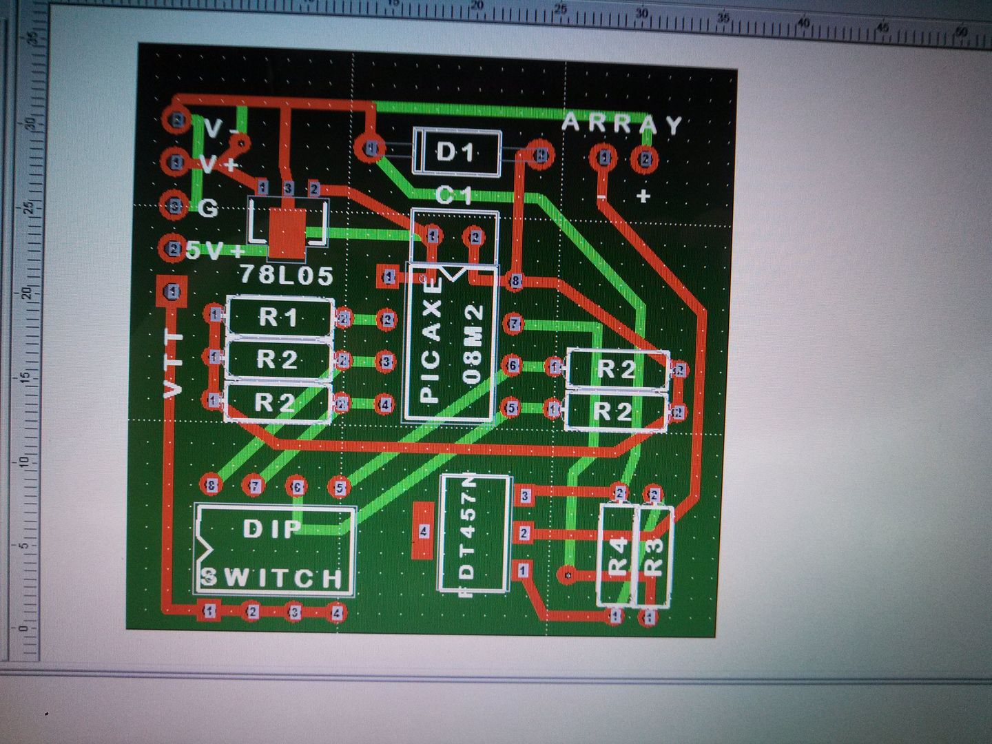
On Roger's system the 4 position dip switch was mounted on the camera with the transmitter. Well I did not want to put the dip switches with the transmitter inside a commercial camera so I devised some new code and new system so the dip switches that controls the Extender Array ON times can be inside the extender instead of the camera. I also used the VTT output on the receiver board instead of the 1 of 4 channels as Roger did. Essentially the VTT goes HIGH anytime the receiver receives a signal. So therefore a single channel transmitter/receiver can be used eleminating the need for a 4 channel set up. Here is a picture of the board in the extender:
Here is the Picaxe code, the times on this code and be easily tweaked to be used on any camera set up. These are for the UWAY VH200B set up:
'Picaxe 08M2 chip
SYMBOL SWITCH1 = PIN4
SYMBOL SWITCH2 = PIN3
SYMBOL SWITCH3 = PIN2
SYMBOL SWITCH4 = PIN1
DISABLEBOD
INPUT 1
INPUT 2
INPUT 3
INPUT 4
OUTPUT 0
MAIN:
IF SWITCH1 = 1 THEN
GOSUB TIME14SEC
END IF
IF SWITCH2 = 1 THEN
GOSUB TIME24SEC
END IF
IF SWITCH3 = 1 THEN
GOSUB TIME34SEC
END IF
IF SWITCH4 = 1 THEN
GOSUB TIME6SEC
END IF
GOTO MAIN
TIME14SEC:
HIGH 0
PAUSE 15000
LOW 0
GOTO MAIN
TIME24SEC:
HIGH 0
PAUSE 25000
LOW 0
GOTO MAIN
TIME34SEC:
HIGH 0
PAUSE 35000
LOW 0
GOTO MAIN
TIME6SEC:
HIGH 0
PAUSE 6000
LOW 0
GOTO MAIN
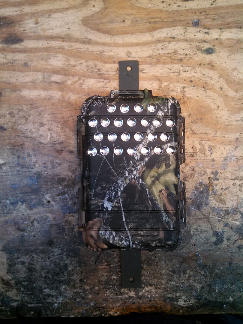
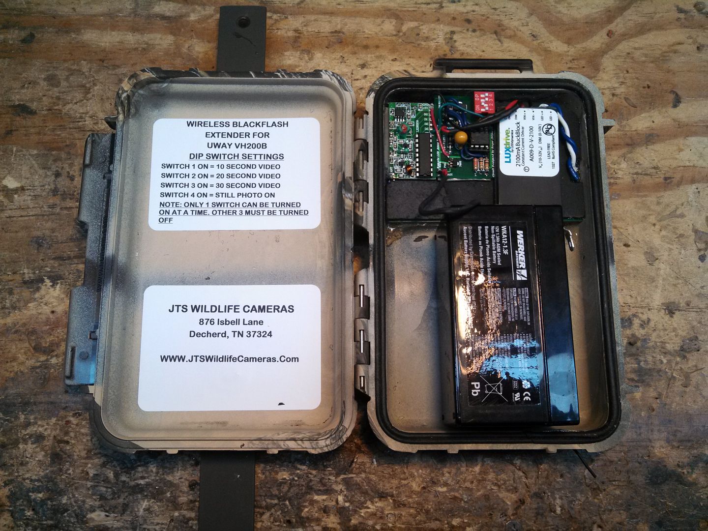
As you can see by the layout on the board and the programming on the chip Pins 1-2-3-4 all are inputs. They are looking for a HIGH signal. The Dip switches control which pin goes high when the VTT output goes HIGH. This works great!!! I learned ALOT while working on this project. Here is a picture of the Actual Wireless Extender Unit. I will post up some videos from the UWAY VH200B without the extender and with the extender tonight.
http://www.hagshouse.com/forums/inde...howtopic=34448
So I started building on what he did. Had some PCB boards built. Man these things work great. Out to 80 feet it works 100% of the time. Adding one to a Homebrew is a peice of cake. No worries at all there. So I decided I wanted to add one to a commercial camera. I got my hands on a UWAY VH200B Blackflash commercial camera and cracked it open. Mounted the transmitter and transmitter board inside it. The UWAY VH200B works on a 10.5v system. So I found some positive and negative power points and wired them in. Next I had to find a power source that was only ON when the LED Array was on. Found that fairly easily. Wired it all up. So I programmed the Picaxe chip on the Transmitter board to turn on the negative side of the Power to the transmitter and to keep that power ON for 2 seconds. Then it takes away the power to the transmitter. All that is needed for my system is a single channel transmitter and receiver. Roger used a 4 channel transmitter and receiver in his project. Here is a picture of the Transmitter board:
Here is the Picaxe Code:
'Picaxe 08M2 chip
Main:
high 0
pause 2000 '2 second button hold
low 0
end
On Roger's system the 4 position dip switch was mounted on the camera with the transmitter. Well I did not want to put the dip switches with the transmitter inside a commercial camera so I devised some new code and new system so the dip switches that controls the Extender Array ON times can be inside the extender instead of the camera. I also used the VTT output on the receiver board instead of the 1 of 4 channels as Roger did. Essentially the VTT goes HIGH anytime the receiver receives a signal. So therefore a single channel transmitter/receiver can be used eleminating the need for a 4 channel set up. Here is a picture of the board in the extender:
Here is the Picaxe code, the times on this code and be easily tweaked to be used on any camera set up. These are for the UWAY VH200B set up:
'Picaxe 08M2 chip
SYMBOL SWITCH1 = PIN4
SYMBOL SWITCH2 = PIN3
SYMBOL SWITCH3 = PIN2
SYMBOL SWITCH4 = PIN1
DISABLEBOD
INPUT 1
INPUT 2
INPUT 3
INPUT 4
OUTPUT 0
MAIN:
IF SWITCH1 = 1 THEN
GOSUB TIME14SEC
END IF
IF SWITCH2 = 1 THEN
GOSUB TIME24SEC
END IF
IF SWITCH3 = 1 THEN
GOSUB TIME34SEC
END IF
IF SWITCH4 = 1 THEN
GOSUB TIME6SEC
END IF
GOTO MAIN
TIME14SEC:
HIGH 0
PAUSE 15000
LOW 0
GOTO MAIN
TIME24SEC:
HIGH 0
PAUSE 25000
LOW 0
GOTO MAIN
TIME34SEC:
HIGH 0
PAUSE 35000
LOW 0
GOTO MAIN
TIME6SEC:
HIGH 0
PAUSE 6000
LOW 0
GOTO MAIN
As you can see by the layout on the board and the programming on the chip Pins 1-2-3-4 all are inputs. They are looking for a HIGH signal. The Dip switches control which pin goes high when the VTT output goes HIGH. This works great!!! I learned ALOT while working on this project. Here is a picture of the Actual Wireless Extender Unit. I will post up some videos from the UWAY VH200B without the extender and with the extender tonight.
 02-11-2014 | 04:26 PM
#2
Thread Starter
Spike
Joined: Jul 2011
Posts: 45
Likes: 0
Here is some test videos I done. They are of me. I could not get my local wildlife to cooperate.
This is the UWAY VH200B without the Extender. Just the camera flash alone.
http://youtu.be/sJ-hA8be1-c
Here is the UWAY VH200B with the Extender mounted 12 yards in front of the camera. The big log that is down is 23 yards (69 feet) from the camera.
http://youtu.be/N-XQVpiuc64
This is the UWAY VH200B without the Extender. Just the camera flash alone.
http://youtu.be/sJ-hA8be1-c
Here is the UWAY VH200B with the Extender mounted 12 yards in front of the camera. The big log that is down is 23 yards (69 feet) from the camera.
http://youtu.be/N-XQVpiuc64
