


CaMirror™
 02-23-2009, 07:37 PM
#11
Typical Buck
Join Date: Dec 2006
Location:
Posts: 654
Man, your ingenuity is really impressive. I've already got one of your presses and now I guess I'll just have to stand by until you work out all the kinks on your "cammirror" tool and put em out. Keep the inventions coming!!
Dan
Dan
 02-24-2009, 04:30 PM
#12
Thread Starter
Join Date: Feb 2003
Location: Alvo Nebraska USA
Posts: 2,057
Thanks for the kind words
Here's the latest version made out of Lexan, tough stuff and a great finish. I think this will be the materal to work with and now I'm small parts hunting. [/align]

Here's the latest version made out of Lexan, tough stuff and a great finish. I think this will be the materal to work with and now I'm small parts hunting. [/align]
02-25-2009, 03:16 PM
#13
Thread Starter
Join Date: Feb 2003
Location: Alvo Nebraska USA
Posts: 2,057
I CaMirrorized my '07 3D Guardian today.. It has been very accurate and shot great last summer. The module stops were hitting at the same time but the CaMirror showed a 1/4 inch difference gap on the top cam as compared to the bottom. I put it in the press and took a turn out, made 1/8" difference for the better. Pressed it again and it was spot on top to bottom. Checked the module stops at full draw again and the bottom cam was late in hitting the stop.
Looking the bow over, the cables cross above the guard rod and the cable angles are very different going to the cams. I then switched the slide upside down and crossed the cables below the guard and checked the cams again for roll over match. They were spot on this time with perfect timing. Guys, we've been setting these bows up all along to stop on the cables that are in the wrong position. What we've been doing is compromizing synchronization at brace to match unequal cable angles at full draw.
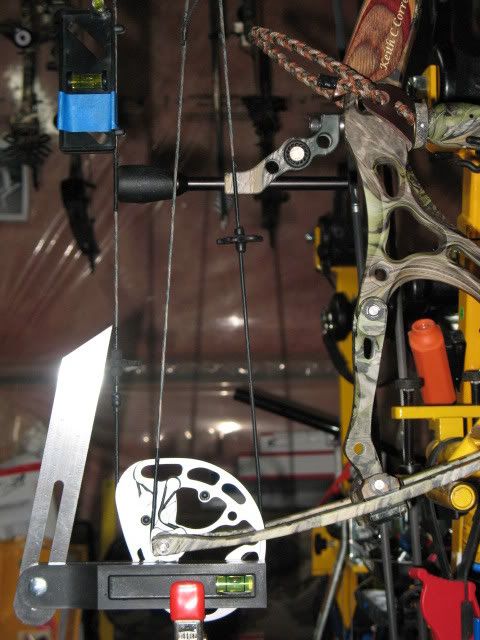
Here's a pic of my Guardian with the cables crossing above the rod as from the factory. It's easy to see that the cable angles are vastly different.Switching them to cross below made all the difference in synchronization at full draw. In reality, if the cams are sync'd at brace they are still in sync at full draw but the unequal cable angles and out of time mod stops make us think they are out of sync.
Here's hoping a change will come soon that has the manufactures making slight changes to the modules that will take into consideration where the cables cross and where the roller guard/cable rod is located.

my '07 3D Guardian today.. It has been very accurate and shot great last summer. The module stops were hitting at the same time but the CaMirror showed a 1/4 inch difference gap on the top cam as compared to the bottom. I put it in the press and took a turn out, made 1/8" difference for the better. Pressed it again and it was spot on top to bottom. Checked the module stops at full draw again and the bottom cam was late in hitting the stop. Looking the bow over, the cables cross above the guard rod and the cable angles are very different going to the cams. I then switched the slide upside down and crossed the cables below the guard and checked the cams again for roll over match. They were spot on this time with perfect timing. Guys, we've been setting these bows up all along to stop on the cables that are in the wrong position. What we've been doing is compromizing synchronization at brace to match unequal cable angles at full draw.
Here's a pic of my Guardian with the cables crossing above the rod as from the factory. It's easy to see that the cable angles are vastly different.Switching them to cross below made all the difference in synchronization at full draw. In reality, if the cams are sync'd at brace they are still in sync at full draw but the unequal cable angles and out of time mod stops make us think they are out of sync.
Here's hoping a change will come soon that has the manufactures making slight changes to the modules that will take into consideration where the cables cross and where the roller guard/cable rod is located.
02-25-2009, 08:50 PM
#14
Typical Buck
Join Date: Dec 2006
Location:
Posts: 654
Let me ask you this and forgive me if this is a stupid question. Will you now tune your Guardian with the cables on the underside and then put them back in the top position (factory) and accept that it is timed?
Dan
Dan
02-26-2009, 05:19 AM
#15
Nontypical Buck
Join Date: Jul 2005
Location: Cogan Station, PA
Posts: 2,298
Interesting. So the two inch radius you're mentioning is from the timing dots to where? The fact that the radius is so small, it doesn't show the errors as accurately or what? I suppose I'm confused as to why using the location of the draw stop modules in relation to the cables at full draw is an incorrect method synchronization? I understand you're saying it's a compromising the synch at brace, but how does that effect arrow flight?
Believe me, I'm not an expert, and I can see you know what you're doing, I just want some clarification. Thanks!
Believe me, I'm not an expert, and I can see you know what you're doing, I just want some clarification. Thanks!
02-26-2009, 06:44 AM
#16
Thread Starter
Join Date: Feb 2003
Location: Alvo Nebraska USA
Posts: 2,057
ORIGINAL: mfd1027
Let me ask you this and forgive me if this is a stupid question. Will you now tune your Guardian with the cables on the underside and then put them back in the top position (factory) and accept that it is timed?
Dan
Let me ask you this and forgive me if this is a stupid question. Will you now tune your Guardian with the cables on the underside and then put them back in the top position (factory) and accept that it is timed?
Dan
 02-26-2009, 07:15 AM
#18
Nontypical Buck
Join Date: Feb 2003
Location: Brampton Ontario Canada
Posts: 1,038
Russ after looking at your system I tried something similar, not as intricate as your idea.
I first squared the bow in a bow vise, leveled all the axis's andthen checked my cam sync. At the bow's static position both cams were in sync.
Guess the old 07' Guardian will be around for years.
I first squared the bow in a bow vise, leveled all the axis's andthen checked my cam sync. At the bow's static position both cams were in sync.
Guess the old 07' Guardian will be around for years
.
02-26-2009, 08:11 AM
#19
Thread Starter
Join Date: Feb 2003
Location: Alvo Nebraska USA
Posts: 2,057
ORIGINAL: ampahunter
Russ after looking at your system I tried something similar, not as intricate as your idea.
I first squared the bow in a bow vise, leveled all the axis's andthen checked my cam sync. At the bow's static position both cams were in sync.
Guess the old 07' Guardian will be around for years.
Russ after looking at your system I tried something similar, not as intricate as your idea.
I first squared the bow in a bow vise, leveled all the axis's andthen checked my cam sync. At the bow's static position both cams were in sync.
Guess the old 07' Guardian will be around for years
.
02-26-2009, 08:26 AM
#20
Thread Starter
Join Date: Feb 2003
Location: Alvo Nebraska USA
Posts: 2,057
ORIGINAL: MGH_PA
Interesting. So the two inch radius you're mentioning is from the timing dots to where? The fact that the radius is so small, it doesn't show the errors as accurately or what? I suppose I'm confused as to why using the location of the draw stop modules in relation to the cables at full draw is an incorrect method synchronization? I understand you're saying it's a compromising the synch at brace, but how does that effect arrow flight?
Believe me, I'm not an expert, and I can see you know what you're doing, I just want some clarification. Thanks!
. However if your bow has an agreeable cable crossing and method of containment like the Guardian. you're probably going to find than module stop matching is right on the money.. The worst of the offenders are the roller guards and don't allow the cables to travel back with the cam axle centerlines. These have much different cable angles at full draw, where you think you need module stop matching